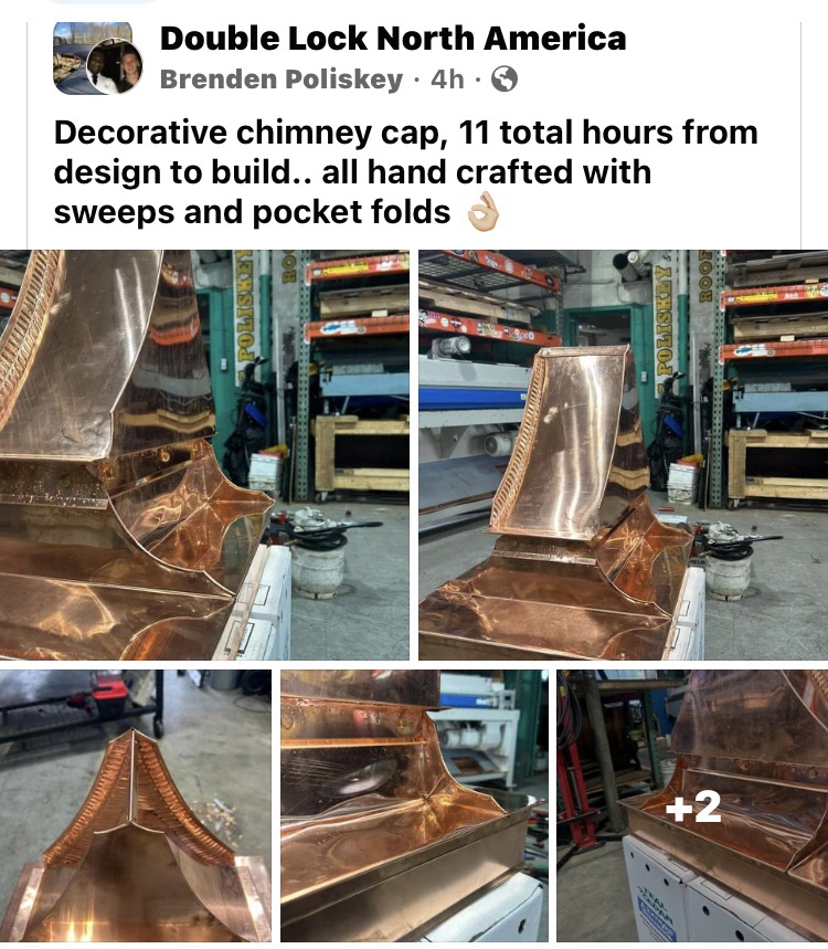
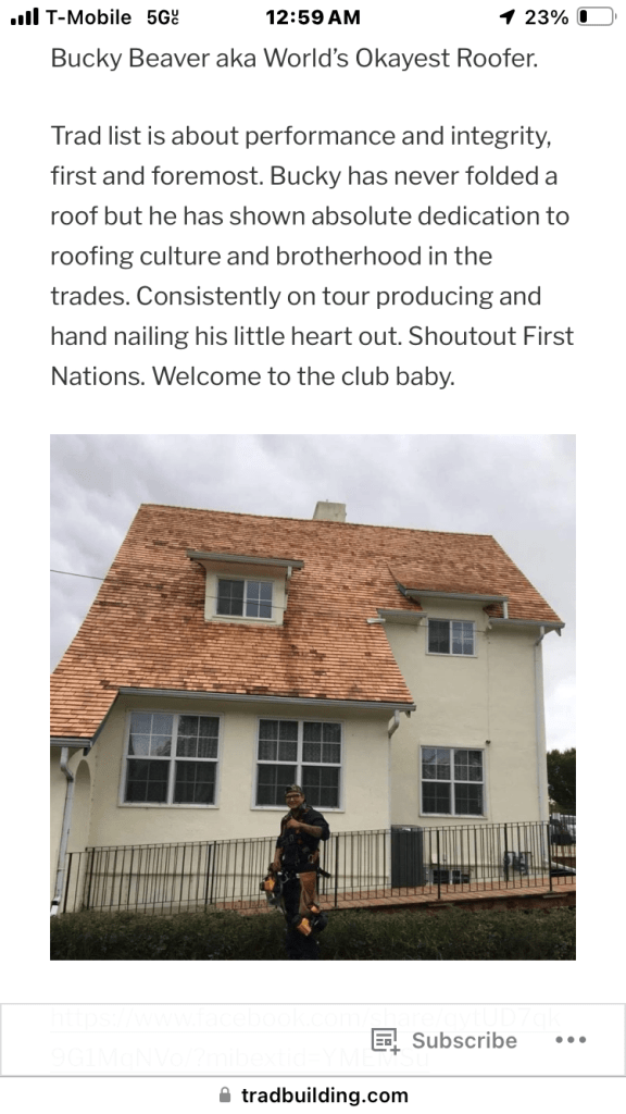
Trad list is open and active if you advertise your work and we see it, you may be considered for jury simple as. the wave we started at tradroofing in North America in 2012 has grown. here’s a little guy Brendan worked on for 11 hours. Quite the task model.
Ask a conservative why Britain’s cities and towns often look so ugly, and you’ll likely be told that it’s intentional: the result of post-war utopianism and the establishment’s inexplicable embrace of modernist architecture. For the traditionalist magus, Roger Scruton, such a development was “the greatest crime against beauty the world has yet seen”. In this account, it is the fanatical architect, zealous planner, and toadyish politician who are to blame for the handsome streets of yesteryear giving way to atomised ruin. The malaise may be aesthetic, but its roots are moral.
What is not asked, however, is why? Why did Britain, and much of the West, suddenly insist on remaking the built environment at such speed? The idea this resulted from a sudden bout of cultural self-loathing is supported by no evidence. The same is true for the notion that despite founding Nato and trying to maintain its empire, post-war Britain was somehow stuffed with surreptitious Marxists, from the commanding heights of Westminster to the planning offices of your local town hall.
Like most simple, comforting stories, this is wrong — a convenient narrative for inaction and self-satisfied moaning. What is needed instead is a Marxist, materialist account of why the built environment changed as it did. History, after all, is not forged purely by ideas.
What does a materialist analysis tell us? Firstly, that conservative concepts of beauty are incongruent with a devotion to the free market, something which Marx identified 150 years ago. Capitalism, driven by a relentless quest for profit, requires constant spatial transformation. This means we have the buildings we do because, for the most part, somebody somewhere is making a buck. This is difficult to grasp for many on the Right because they have elevated profit into a kind of ethical value (although this wasn’t always the case). But it should be relatively obvious, and far less outlandish than the idea that your nearest Wilko or TK Maxx looks the way it does because of the malevolent influence of Oscar Niemeyer. As Marx wrote in The Communist Manifesto: “All that is solid melts into air; all that is holy is profaned.” This is why a commitment to the free market, and to social and aesthetic conservatism, are irreconcilable.
This is most conspicuous today with Purpose Built Student Accommodation (PBSAs), those modular ziggurats afflicting skylines across Britain, from Altus House in Leeds to Beckley Point in Plymouth (each is the tallest building in their respective city). In Cardiff, more than 7,000 student “flats” were built in just three years.
These buildings are springing up like medieval Bolognese towers for two reasons: firstly, because the building standards are lower for student developments than either residential housing or housing in multiple occupation; and secondly, because building them is lucrative. Forget Marxist council officers and architects with fantasies of becoming the next Frank Gehry. These buildings are being assembled in the quest for profit.
In Portsmouth, the city centre has now essentially become a student campus, the city’s sense of civic pride sacrificed to corporate student accommodation and fast-food outlets zipping deliveries to them via smartphone. It’s a grim vision of what our smaller city centres are becoming, with spaces for interaction in short supply. In Bournemouth, where I grew up, a seaside town synonymous with Victorian and Art Deco architecture looks increasingly like the set of the Teletubbies. Any sense of place is out of the question, the objective instead being to turn the town into a giant airport terminal.
Another important reason for those tragic “before and after” pictures so beloved of Trad Architecture Twitter is the popular adoption of the car in the mid-20th century. As with the failure to grasp the contradiction between free markets and conservation, this too is lost for many on the Right (although, in his defence, Scruton once referred to cars as “dangerous weapons”). This shouldn’t be overly surprising given the automobile was synonymous with personal freedom, an avatar of the sovereign individual conquering the elements. What is forgotten with this blanket projection of personal autonomy, detached from society, is that the dense patchwork of urban settlement that preceded it was lost. You may be able to go anywhere in a car, but you do so by cutting yourself off from others. In the words of Kafka: “you are free, and that is why you are lost.”
The reconfiguration of streets around the car is the principal reason cities such as Birmingham, Glasgow and Bristol lost much of their lustre. This was not limited to Britain, of course. Take the story of Robert Moses, the subject of Robert Caro’s magnificent biography The Power Broker. Over several decades as a public official in New York, Moses gleefully destroyed downtown areas often marked by cultural and racial diversity, as well as high density construction. The reason? To build expressways.
The Cross Bronx Expressway offers the best example of this, ripping as it did through the heart of what would become the northern and southern parts of the Bronx. Things could have been worse, however. And it was only because of civic resistance, led by the likes of Jane Jacobs, that the construction of the proposed Lower Manhattan Expressway was stopped. Had she failed, it would have destroyed much of what is SoHo, Little Italy and Chinatown.
While it’s true that an infatuation with the car was central to post-war planning, today it is the Left leading the movement for low traffic neighbourhoods (LTNs). By contrast, it is Conservative councils, such as inSouthampton or Wandsworth, that are reversing them. This is not to say all LTNs have been executed well, but it is clear that reducing our dependence on cars has become a part of the culture wars, with conservatives often on the wrong side. It’s one thing posting nostalgic pictures of yesteryear; it’s another to do the hard political yards to reverse mistaken choices since.
This bizarre confusion is most obvious in Poundbury, the experimental community built on land belonging to Prince Charles. Even here, in a place whose premise is a return to tradition, the civic centre of Queen Mother Square is a car park. Even if you embrace the orthodoxies behind the project (I personally find it more akin to a Las Vegas theme park), it’s hard to see how rows of hatchbacks and people carriers continue the legacy of Victorian or Georgian architecture. It’s the same in the village of Wickham, home to the second largest medieval square in England. The Visit Hampshire websiterefers to the village’s “15th century cottages” and “beautifully preserved Georgian houses”. Yet such wonders are also now obscured by the fact that the village square is now a rather large car park.
When it comes to the built environment, it’s easy to lapse into mistaken binaries. On the Right, conservatives wish to retain a distinctive architecture. They claim to want to “conserve” buildings whose qualities transcend present, fleeting sensibilities. They believe in objective standards of beauty — be they from antiquity, or the work of Palladio or Wren. The Left, meanwhile, is apparently driven by a fixation with the future, a permanent experimentation with forms and an impulse to discard the old.
And yet much of this narrative doesn’t align with reality. Councils of all stripes are gleefully granting permission for hideous student blocks, while a Conservative government oversees our rivers being pumped with effluent. Meanwhile, it is progressives who make the arguments for more humane environments where we use our cars less and enjoy a slower pace of life. They don’t always get everything right, but there should be no doubt that active travel, living streets and low traffic neighbourhoods are the simplest ways to begin making our towns and cities beautiful again.
All of which is why the socialist case for respecting architectural heritage should not be at odds with a small ‘c’ conservative approach. This should be the opposite of the promethean road-building projects of the last century, while also avoiding a swivel-eyed hatred of more recent architectural heritage, whether that be the Barbican in London or Berlin’s Palace of the Republic. Take the brutalist Trinity car park in Gateshead. Conservative critics may think such buildings shouldn’t exist by default, and so it was demolished in 2010. Yet it has been replaced by a Tesco — hardly a win for Scrutonian beauty and the public good.
Finally, socialists and conservatives alike must understand that the built environment, as with every human endeavour, is an inheritance from one generation to the next. We should be humble rather than dismiss the ideas of those before us, regardless of which century they come from, while also asking what kinds of structures will fill our descendants with wonder. As Stephen Nachmanovitch wrote: “If we operate with a belief in long sweeps of time, we build cathedrals. If we operate from fiscal quarter to fiscal quarter, we build ugly shopping malls.” The enemy of beauty isn’t “modernism”; it’s a society built on maximising profit and shareholder value.
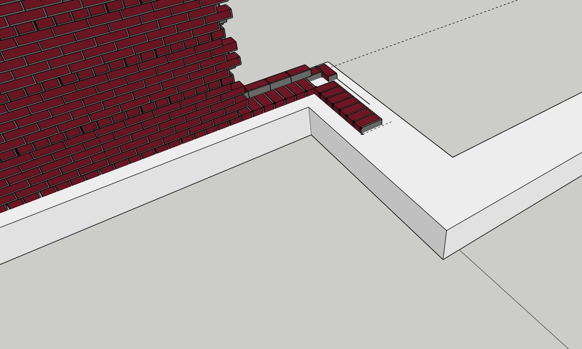
Panels “lining up” – also a symptom of modern metal roofing. Since they are not intersecting pans and interrupt them for z bar and cap, it’s customary and considered workmanlike to align the pan seams on either side of a hip, or ridge. In seamed work, this is the opposite because folding two intersecting seams into a double lock is very difficult and provides no added value. It is sometimes done by very good folders to “show off” essential how perfect their notching is, but generally it’s frowned upon because again it adds risk, (of folds not completing well) with no added value other than aesthetics. – Kurtis Hord
I’m working on a new video for this. It’s a poor lesson because it doesn’t explain the WHY. First of all, nominal standards have been with us since the civil war and balloon framing boom. This was directly influenced by two things: the railroad and the green bar on the architect’s scale. The nominal dimensions of stick framing lumber are chosen to fit checksums within the 3/4 per inch scale.. even when boards were planed 7/8 or 1” that is still in the scale. All of this in the effort to use wood to compose cornice and stone building forms. Nicholson and some other “revivalist” 18th century treatises wrote whole books in the practice of specifying nominal dimensions from the desk which would translate to “shrunken” classical orders appropriate for wood.
That explains the shape… and size.
As for the quality and performance.. thats a whole book…. I would read “American canopy” if I were me. that’s all based on how the tree grew. And how it was chosen to be sawed. Plantations and monoculture logging produces poor timber products. The trees should mostly be left alone. Managed for biodiversity and maturity and harvested ethically for permanent building intents only.
Some notes on the actual forensics of each section. The 1920s tree is a young tree super fast growing, so it likely grew from clearcut. It would never be a good beam. It has a use at this age: They chose it for this purpose to be a stud, or vertical member of a superficial wall.
The 60s section is a slow growing tree, with a lot of integrity so likely logged from the west or north. But it was methodically production cut into a modular unit with no regard to grain direction or function. It could have been as well, beams or bearing planks, but was sold as a superficial stud.
The modern commodity lumber is made that way to “make line go up on a balance sheet.” It never should have been harvested.
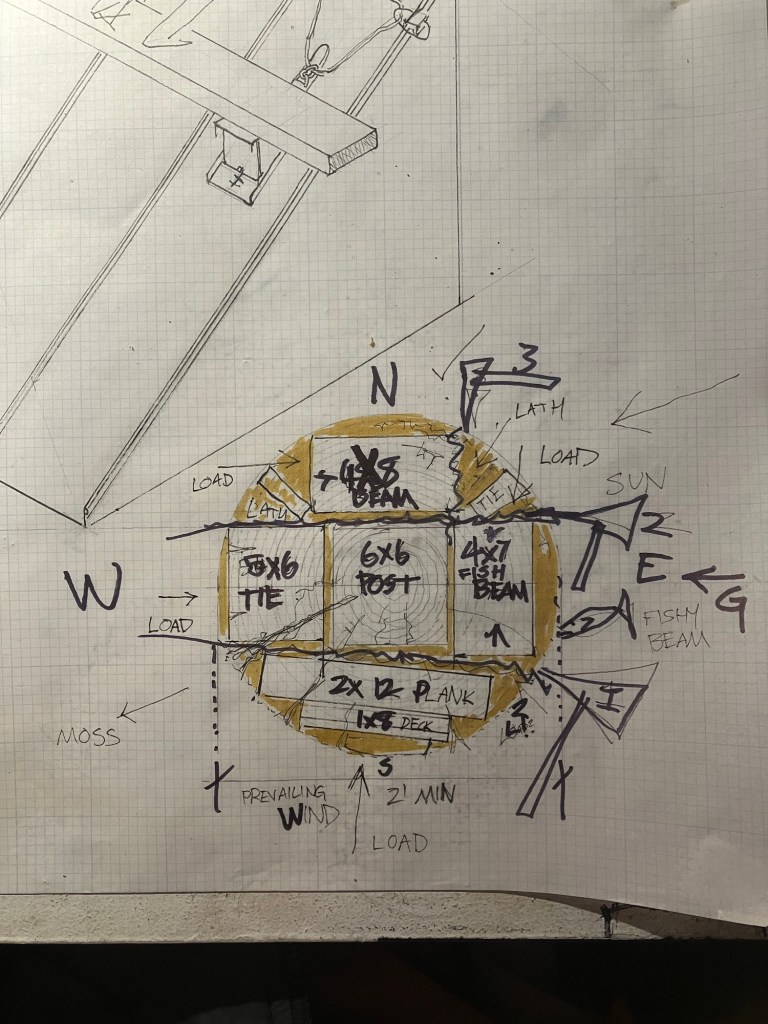
How to judge a tree with human power for permanent building.
Wood from trees is judged accordingly: first you find a tree at least 2’ in diameter.. you look for the prevailing wind and spring line. You mark the tree on that axis and injure it to the sapwood. You come back the next season to Harvest it. Simple as.
How to grade cross sections for building units:
Beams: beams come from the spring line they have grain running parallel to the load. And they are growing towards the sun and crowned by the wind loads.
Post: post are the heartwood, they have compressive strength
Ties: ties are from the quarters. They have grain running at skews to the face. Great for cross joinery and tension.
Planks: planks are the strong back of the tree, the section which bent and stretched the most. Perpendicular to spring line with grain running in an arc across the load center.
First is the study of architecture itself. At the material and labor level of operations Architecture is simply programming or planning what will be, before it occurs.
This is why we call them the “specifier” class now. In trad building you learn by specifying your own labor first. then you practice by testing that labor and performance before a jury of elders.
In this way trad building is much like solo climbing. A mountaineer would be disregarded if they stayed at base camp and simply specified the efforts of sherpas on the mountain. We would not allow them to take credit for the ascent. Yet the entire field of professional architecture is built on this premise..
Buildings require planning and labor to occur. They do not require a specifier class however. The specifier class requires itself.
Task model in “classical”: stereotomy proof for square groin vault surface.
Task model combining stereotomy of surface and solids (framing joinery)
So what is required? Well, start by setting off a task model. Here is an example of a task model:
Build a 1000 year lifespan “Roman” floor 10×10 encased within 2 wythe bonded wall. Record total calories in and man hours. Derive a ratio to describe the building as total calories over expected lifespan. Translate to modern price per square ft metrics.
Ingredients: quicklime; brick, earth, gravel
Tools: typical pre industrial methods and tools with power assist practically applied where process is not effected.
Task model in mineral binders: floor base, 3 bucks per square foot. wall section, 35 bucks per cube foot.
Joseph Aspdin’s 18th century Leeds was an infrastructure boom town due to the textile trade. Him: a bricklayer with no access to common stones found himself collecting precursor for cement by literally sweeping slaked lime dust (chalk) from bountiful waste products of road repairs. Collecting the stone road work-site dust by the 1/3 ton was enough work for anyone. But then: This dust by itself could not be fired in a kiln to make it alive again…. And who wants to work that hard anyway…. Instead he would make a slurry of the lime dust and clay heavy earth, pour it out and dry it, then those hard chunks of clay and lime could be fired much like any other. Once they were fired and ground down: you have your hydraulic cement.
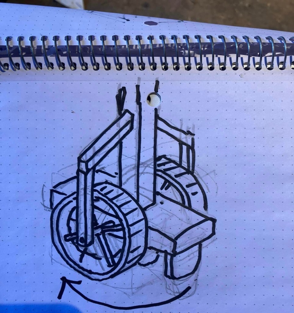
Remains of a Saxon concrete mixer discovered in Britain show that shallow bowls were cut into bedrock, with a central post of timber. A wooden beam with paddles rotated about the central axis to mix the concrete. Labor was supplied by humans, as shown here, or by animals such as oxen or horses.20th century plaster pug mill, 1910 Iowa
Here’s a shocking thing maybe if you’re not a student of Nigel Copsey: this method was not new. It was used all thru the supposed “dark ages” all over the continent. Known as trass, water lime, ditch mortar, and wrongly known as “concrete”. It was used for floors, setting tiles, and water works. Nobody ever needed to rediscover Vitruvius in a monastery to know basic human building technology. The myths of “lost arts” are just that. Myths invented to sell class status and deskill labor.
It was pure scarcity that drove Aspdin away from craft practices, as his peers and competitors knew: the “Roman” method involved exploiting the hot mix reaction of quicklime combined with a hydraulic pozzolan dust to bind with the lime seeking air. The royal philosophers and scientist had access to experimental time. They classified pozzolans in vast tables and assigned numbers and latin names to every fucking stroke of the flask and flame down to the mole and calorie. Aspdin did not have access to much free stone to burn for quicklime, he was even arrested twice in his life for stealing stones from the roads themselves. Smeaton and Robert Scott Vicat and a whole murderers row of ghouls and industrialist will dance on the same subject.
“First” concrete bridge. Joseph and Louis Vicat in Grenoble’s Jardin des Plantes in 1855
At the end of the research you find a bunch of myth making and grubstaking by the “winners” of building history to enclose upon and institutionalize what are two methods of action in chemistry involving just a few discrete steps and feedstocks. Mineral binders are only created and function two ways: either thru the quicklime /water reaction, and set thru exchanging air. Or thru exploiting the pozzolanic reaction and cold clay/calcine reaction, in the case of Portland cements.
In the grand tradition of labor guild battles Josh Bigger has entered sacred ground with claims made before god. We call upon our lord to observe dutifully and take notes.
My man wanted attention from God.. he got the pope instead.


You must be logged in to post a comment.