
rob unversaw of Rockdale Construction: framing plan fail
here is what Robbert built.
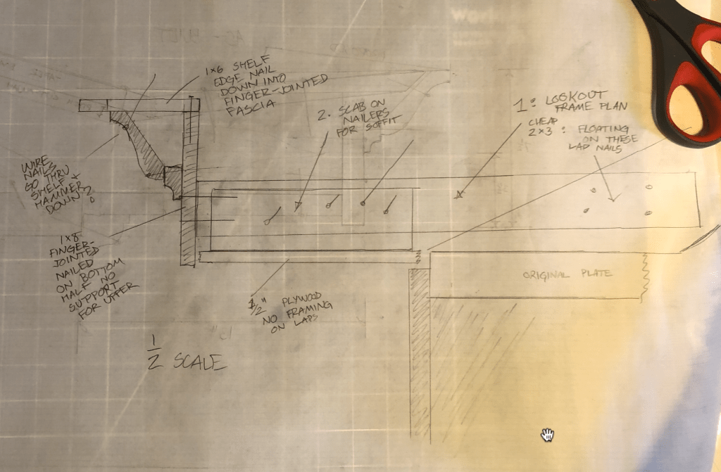
truly shameful and unprecedented. The lookouts were floating, lap-nailed. The sill under, rotted in many places. The shelf and cornice is held on by finger jointed interior trim, wire nailed to end grain. All of the historic wood which needed to be stripped and repaired right, was glued together with another layer of caulk and spray on paint.

Trad Building
Styling an addition to a Victorian wood house
I don’t care for stick frame wood houses from any era: but here we are stuck with them all over the landscape. These structures have far less integrity than brick or stone. Most of them can be expected to last 16-20 generations. About 1/3 of the lifespan of a comparable brick structure. Thats still enough lifespan to justify preservation though, for the good examples of the building method.
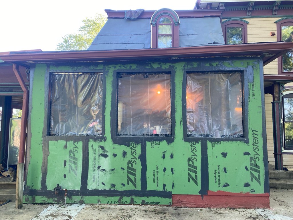
This challenge involved taking a 20th century porch addition and styling it to make sense with the rest of the house.
My first idea was to punctuate the addition and date it in the arts and crafts era. The theory being: an addition should read as an addition and not attempt to “fake” consistency with the rest of the building:


This design features a shiplap lower apron, continuous sill, and stucco wall finish. Simple 1×6 trim for the windows.
The next design is more in keeping with the style of the house. It features a paneled layout with the trim reduced and pilasters defining the layout. The corbel brackets from the main cornice are repeated here and carved half-round reliefs are used to give the trim pilasters some texture.
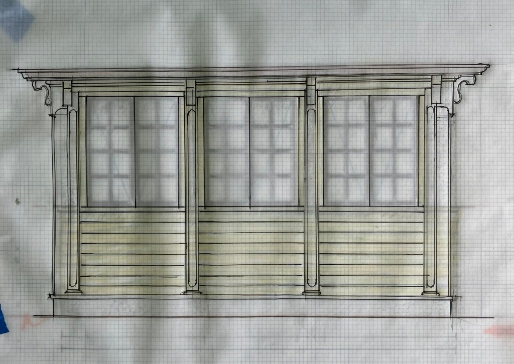
The “fancy” one would take nearly double the labor and demands high grade materials for the sill, moldings, and pilasters so it’s a real show off, for a small addition to an already grand structure.
Arts and farts.


Correcting a half-cooked McMansion with proper structural methods and regional pattern language.
The first draft featured a misguided mansard, 2 wythe wall, foam, veneer walls, concrete slabs, false walls and drywall, and a horrible user experience within the floor and stair plan.
The building as designed by Pless is no better than a typical office/commercial structure. Consuming a lot of barcode materials and proprietary engineered “structure”.
This revision maintains the “impressive” symmetrical entry but cleans up all the appliqué. The garage structure is no longer an appendage with the same roofline. Instead it’s punctuated as a utility building separate from the main. Using a mews pattern with parapet gables.
The bloated lawyer foyer is gone and in its place is a classical 3/4 stair with a landing at the lantern window over the front entry.
Gone is the fake cornice. In its place is a brick corbel, and simple soffit and fascia with a standard hung gutter inset to stand as the cyma recta.
Midweek update
There hasn’t been too much photogenic work since I completed the tiny bathroom. In the last weeks we moved a bunch of dirt, did grounds work, cleaned and performed quarter-making duties.

The “apartment” is almost livable with a few quirks remaining. I have to perform extra labor to hang dry clothes and I’m chopping veg on a short table instead of a waist high counter-top. Theres no freezer so i travel on the bike to pick up ice. I can’t store any meals for deep freeze. There’s no stove or oven just a toaster oven and microwave. Meal planning and level of service available to guests is very low class because of these constraints. I certainly can’t invite good people over for dinner in this mess. It’s a lot like being on a ship when you live on location.

The dust and remediation of lead pollution topsoil is nearly complete.
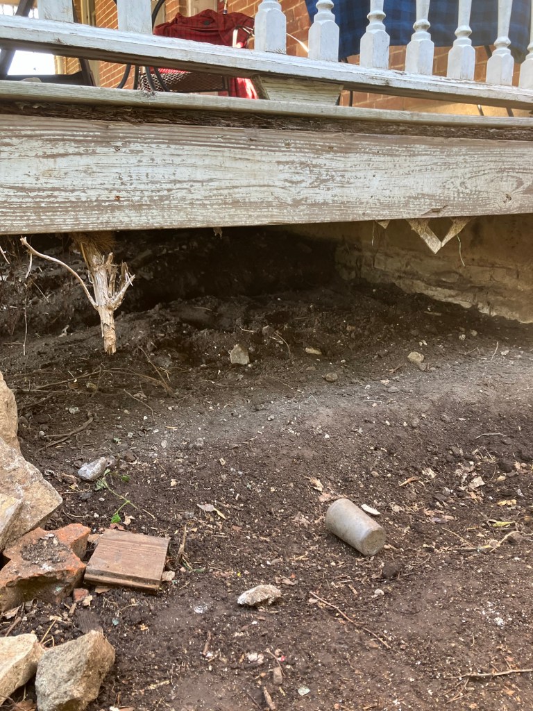
Next task: dig out completely under the porch and tuck point the wet foundation with hot mixed lime mortar. It will be sound for another 7 generations after that work.


Weekend update


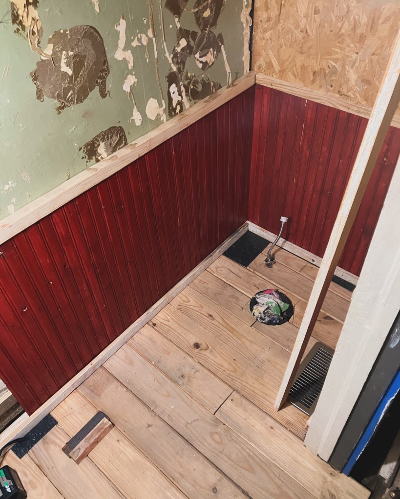
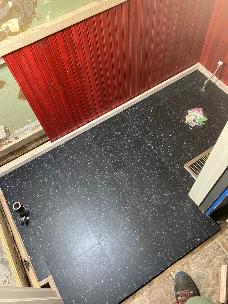
Things are cooking here at the North Star of Winfield. We finished the half bathroom walls, trim, and flooring..

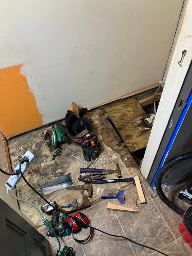
I started Friday morning laying on my back in the hole tacking up pipe straps and eating cobwebs and dust for breakfast…

Justin kept me motivated and ran cuts while I was fussing with the heavy tongue and groove flooring. Todd learned how to bullnose a rail with a palm sander. Everyone got red deck stain all over their hands…
My next job after the bath is finishing the As-built historical documentation. It is nearly complete but I have a few more built-ins and doors to document before they are dismantled for paint stripping….

In the wee hours during the hail storm I inked in this perspective cutaway of our main public room, the east door delivers you to the business center and service counter.. and a small dinging area with a armchair 2-top and 3 top cafe table in the bay window.
The west door leads to the bar and large dining room, with several 2-tops, bay window 3-top; and a large 4-top booth anchored on the west window.

Weekend update

This weekend we really got to work together like a team. Justin helped me keep this jobsite clean, ran the vacuum and handed me water cigs and tools while I was crouched in the hole.
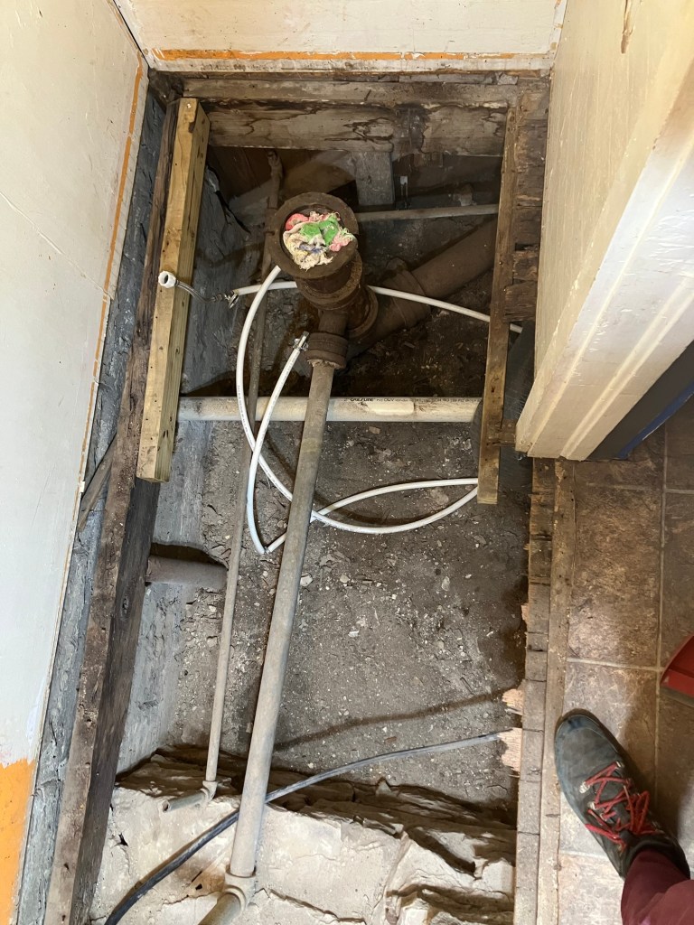
He learned how to remove a toilet without spilling water everywhere, dismantled multiple layers of flooring and patches. We made one trip to the big box store for fixtures and finishes, and one trip to the lumber yard for framing and flooring lumber.
I will complete the framing and install the fixtures and flooring this week. The whole family comes down next week and we will get to paint the trim and decorate/pick a ceiling color.

By god we will have one finished room in this house. Come Saturday we will be shittin’ pretty in the restored half-bath.

Weekend review
TO: Justin / FROM: Kurtis


I woke up early Sunday. Greeted by a train whistle and just the crickets. In the still morning air you can hear dew dripping off the Lady and quenching the yard. Everywhere I look things are proper. put away stored with care, stacked, counted. This indeed looks like a happy house and a place where some very capable men are working
I want to personally thank you, Todd, and Justin once more for your performance this weekend. The grounds feel inviting even though it’s a jobsite. I’m very impressed with your work ethic.
Thank you for respecting my leadership and allowing me to bark orders at you like a mean navy dyke. It was truly an honor to mush you dickweeds around. Looking forward to every session. Even the shitty ones.
The ladies in the wall are extremely happy with how their house is looking.
-Sincerely, Kurtis Hord, Caretaker and Producer
Old Depot Public House.


You must be logged in to post a comment.