
I will be publishing “solutions” from Neubecker’s layout bible: The Universal Sheet Metal Pattern Cutter, vol 2.
This lesson is from section 4: PATTERNS FOR SHEET METAL CORNICES, RETURN, FACE, BEVEL AND BUTT MITERS, PANELS, MOLDINGS, PEDIMENTS, DORMER AND BAY WIN
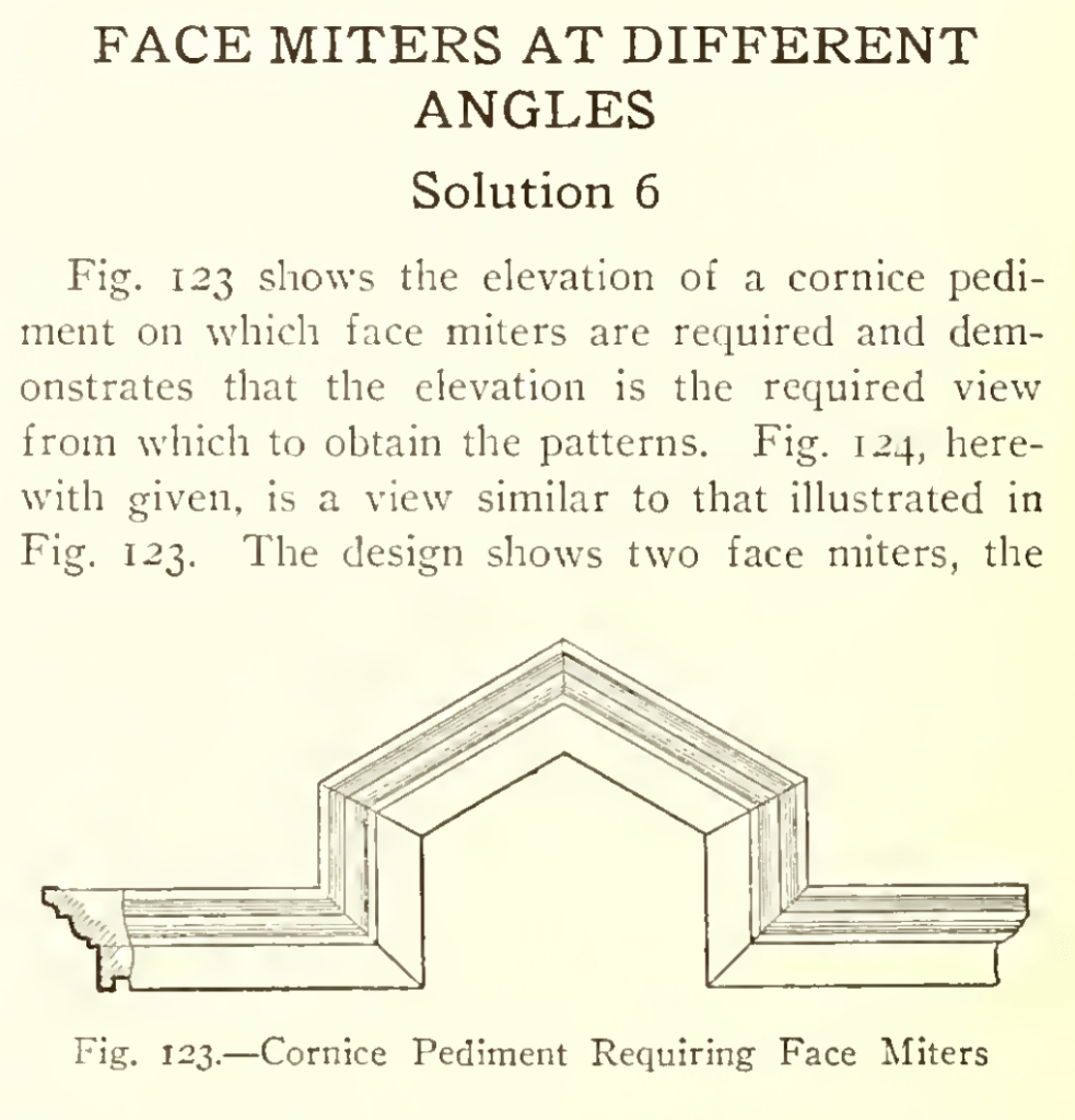
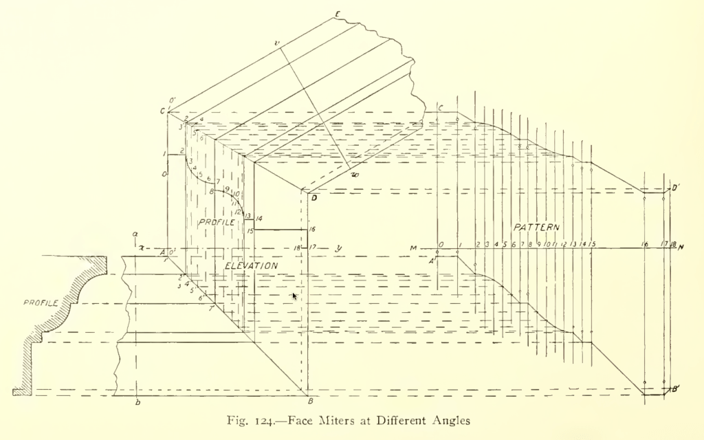
In constructing the view in Fig. 124,
first draw the profile as shown at the left
and from the several angles project lines indefinitely to the right, to begin the elevation.
From A erect the perpendicular A C according to requirements.
On x y, drawn horizontally, set off the spaces found on the perpendicular a b, and through the points thus obtained on x y, draw other perpendiculars to cut the lines first drawn, as shown from A to B.
As a verification of these intersections, it should be noticed that the line A B must be at an angle of 45 degrees and that all the intersections must fall on this line. F
From C, draw C E at the required angle and draw v w at right angles to C E, upon which repeat the spacings on a b as before.
Through the points thus fixed, draw lines parallel to C E to intersect with the vertical line just drawn, thus establishing the position and angle of the miter line C D.
Since both arms of either one of the miters shown are alike, we can economize labor by developing the pattern for the middle piece, duplicating the other arm of the oblique miter from the upper end of the pattern when obtained and that of the square miter from the lower end of the same pattern.
Therefore divide each of the curved portions of the profile into any convenient number of equal spaces, numbering the points of division as shown by the small figures, and set off a stretch-out of the entire profile on a line drawn at right angles to the lines of the elevation of the piece being developed, as shown by M N.
Draw the measuring lines through the points thus obtained as shown, which must be numbered to correspond respectively with the points on the profile.
Project lines from the several points of division on the profile, parallel to the lines of the mold, to intersect the miter lines A B and C D, as shown, and,
finally, project lines from each of the points of intersection just obtained on the two miter lines to cut measuring lines of corresponding number in the stretch-out,
when lines traced through the points of intersection thus obtained, as shown from A1 to B1 and from C1 to D1, will, with the line A1 C1 and B1 D1 constitute the pattern.
One of the principal sources of failure to get correct results in miter cutting is carelessness in the numbering of points.
The profile should in all cases of miter work first be divided into spaces and numbered consecutively from one end to the other. Then each point on the stretch-out line (M N) should bear the same number as the point which it represents on the profile.
If any difficulty then arises, each point on the miter line can also be numbered to correspond with the point from which it was obtained on the profile, as indicated by 1′, 2′, 3′, etc., on either miter line.
After this there should be no trouble in projecting the several points on the miter line into the proper measuring line of the stretch-out.

You must be logged in to post a comment.