Protected: Library Books


The Internet's Own Historic, Traditional, and Permanent Building HQ
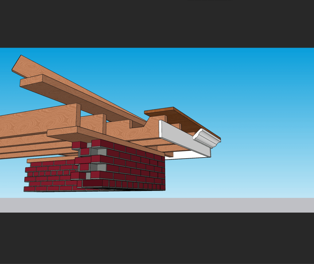
My First day “on the job” in building, for Tom Boone, we were restoring a big wide cornice 60 feet up with a built in gutter. That was New Years day, 2007. It has been the most requested help item from the beginning of my career till, last week! The dang things seem to be so elusive for folks to understand without a historic preservation degree or decades in the field…
Allow me to share my attempts to capture the parts and pieces of the cornice gutter with some rude modeling..


The original book on box gutters:
http://quo-animo.blogspot.com/2008/10/book-on-box-gutters.html


France in the 16th century was a place and a time where big wooden beams were expensive and barely available (*). The classical way of building, with big wooden trusses, was not an option anymore. In his book «Nouvelles Inventions Pour Bien Bastir Et a Petits Fraiz» (Ed.1561), Philibert de l’Orme described an alternative way of building, which is as simple as effective.
With still affordable and available short wooden battens, about 1.30m long, he managed to make huge roof spans, by a very clever “meccano” method of “nailing” them together with dowels. This is a solution which can be seen as the precursor of modern glulam beams. Scarcity of materials as a driver for a circular economy.
Only two types of these battens were needed. Prefabrication of thousand exactly similar wooden pieces could take place in a very cost-efficient way. Modularity as a characteristic of a circular economy.

Illustration : Ph. De l’ Orme, dans «Nouvelles Inventions Pour Bien Bastir Et a Petits Fraiz» (Ed.1561) ; only two types of prefabricated battens are used.
Whenever a piece of wood was infected or broken, it could easily be replaced by a similar one, without the need of breaking down a whole structure. Interchangeability and reversible joints as a characteristic of a circular economy.
Above all, by designing the roof in a form of an arch, or in the form of two arches (like an inverted boat-hull), the material is optimally used. There is no material underperforming its maximal strength. A clever design and a dematerialisation are the first steps in, and the key-factors of a circular economy.
Even though aesthetics were surely not considered to be important in the design of barn roofs in the 16th century, they do play a role in giving a building or building materials multiple lives. And this is what circularity in the design and construction is about.

The barn of Chateau de Maurier, Fontaine-Saint-Martin (F) , architect unknown, inspired by Philibert de l’ Orme, photo : BLIEBERG Architects of a circular economy
Philibert de l’Orme, once a famous architect on the court of Henri II (who designed e.g. the ballroom of the castle of Fontainebleau), fell in disgrace after the death of the monarch. Two years later, he wrote an appendix to his written chef-d’œuvre in which he gave a solution for people who could not afford expensive methods of building.
Kris Blykers, BLIEBERG architects of a circular economy http://www.blieberg.eu
USMPC VOL2 – William Neubecker
GET YOUR HOUSE RIGHT – Cusato
HOT MIXED MORTARS – Nigel Copsey
SLATE ROOF BIBLE – Joe Jenkins
I will be publishing “solutions” from Neubecker’s layout bible: The Universal Sheet Metal Pattern Cutter, vol 2.
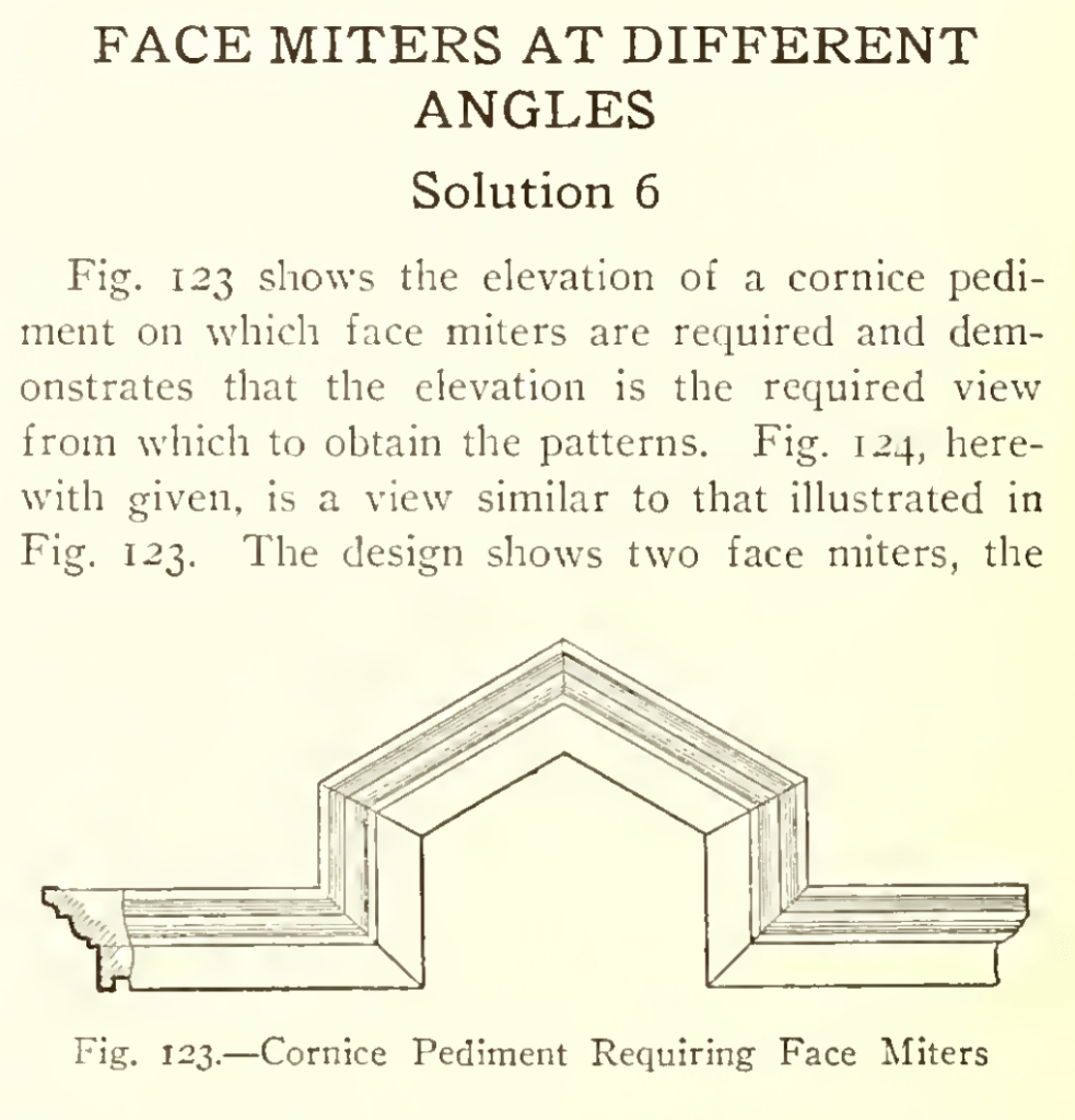
This lesson is from section 4: PATTERNS FOR SHEET METAL CORNICES, RETURN, FACE, BEVEL AND BUTT MITERS, PANELS, MOLDINGS, PEDIMENTS, DORMER AND BAY WIN
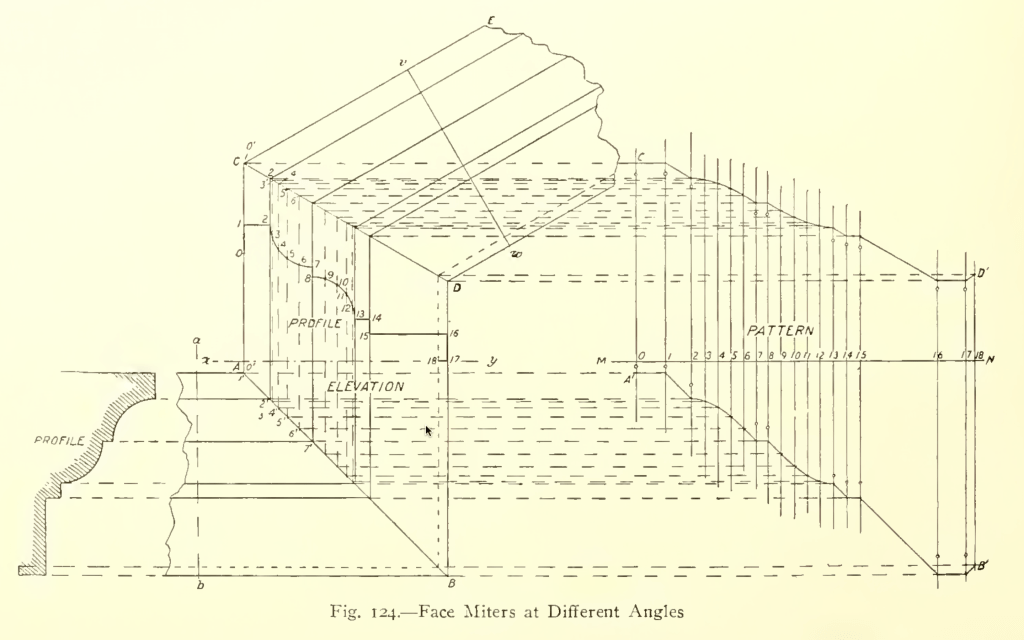
In constructing the view in Fig. 124,
first draw the profile as shown at the left
and from the several angles project lines indefinitely to the right, to begin the elevation.
From A erect the perpendicular A C according to requirements.
On x y, drawn horizontally, set off the spaces found on the perpendicular a b, and through the points thus obtained on x y, draw other perpendiculars to cut the lines first drawn, as shown from A to B.
As a verification of these intersections, it should be noticed that the line A B must be at an angle of 45 degrees and that all the intersections must fall on this line. F
From C, draw C E at the required angle and draw v w at right angles to C E, upon which repeat the spacings on a b as before.
Through the points thus fixed, draw lines parallel to C E to intersect with the vertical line just drawn, thus establishing the position and angle of the miter line C D.
Since both arms of either one of the miters shown are alike, we can economize labor by developing the pattern for the middle piece, duplicating the other arm of the oblique miter from the upper end of the pattern when obtained and that of the square miter from the lower end of the same pattern.
Therefore divide each of the curved portions of the profile into any convenient number of equal spaces, numbering the points of division as shown by the small figures, and set off a stretch-out of the entire profile on a line drawn at right angles to the lines of the elevation of the piece being developed, as shown by M N.
Draw the measuring lines through the points thus obtained as shown, which must be numbered to correspond respectively with the points on the profile.
Project lines from the several points of division on the profile, parallel to the lines of the mold, to intersect the miter lines A B and C D, as shown, and,
finally, project lines from each of the points of intersection just obtained on the two miter lines to cut measuring lines of corresponding number in the stretch-out,
when lines traced through the points of intersection thus obtained, as shown from A1 to B1 and from C1 to D1, will, with the line A1 C1 and B1 D1 constitute the pattern.
One of the principal sources of failure to get correct results in miter cutting is carelessness in the numbering of points.
The profile should in all cases of miter work first be divided into spaces and numbered consecutively from one end to the other. Then each point on the stretch-out line (M N) should bear the same number as the point which it represents on the profile.
If any difficulty then arises, each point on the miter line can also be numbered to correspond with the point from which it was obtained on the profile, as indicated by 1′, 2′, 3′, etc., on either miter line.
After this there should be no trouble in projecting the several points on the miter line into the proper measuring line of the stretch-out.
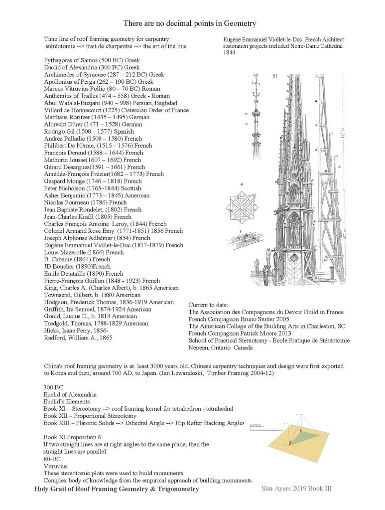
One of the greatest minds alive for traditional building techniques, Sim Ayers


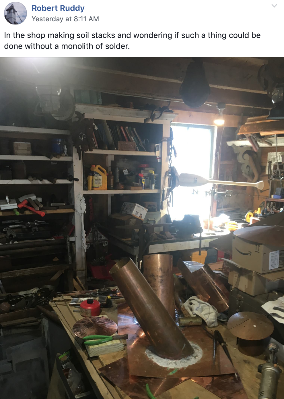
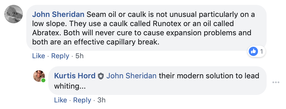
I’ve been meaning to update the site with better organization. Robert’s question and this discussion about seamed pipe boots was the motivation I needed… There are a lot of videos on Youtube, but they are mostly in foreign languages and even alphabets, making a search for trad roofing techniques very difficult for english-speakers. I’m starting to compile the best videos on a new page here: https://tradroofing.wordpress.com/how-to/
Here’s our discussion from the Trad Roofing forum and the video another member of the group submitted to help with his journey: https://youtu.be/w7lAFq7j3qg


You must be logged in to post a comment.