Solution 35, William Neubecker VOL 2

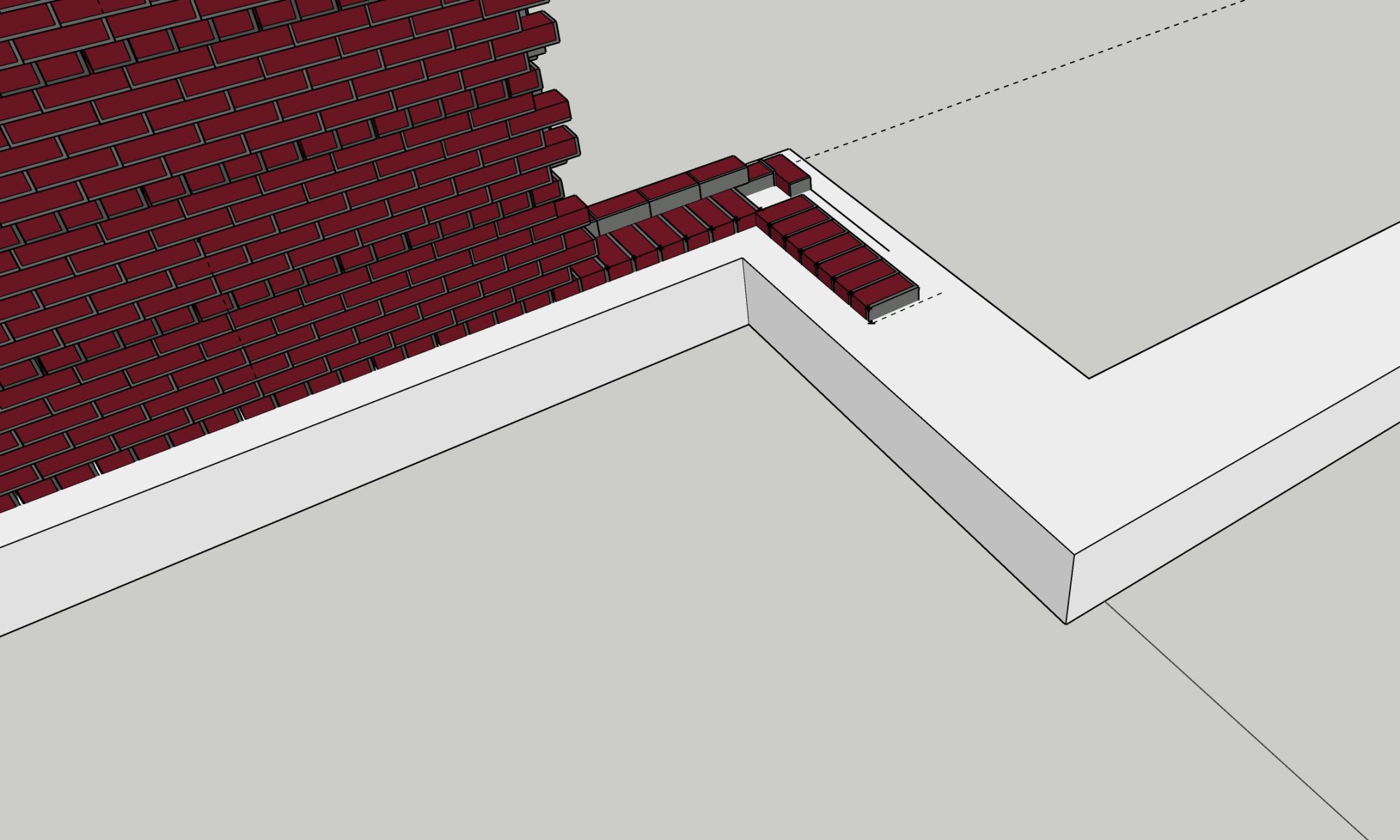
In the example of a gable mold intersecting a molded column, shown in Fig. 201, there is an intersection between vertical and inclined dissimilar moldings.
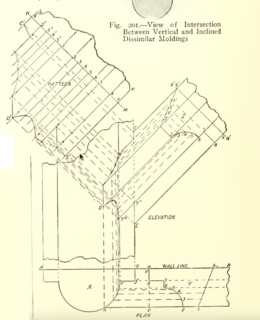
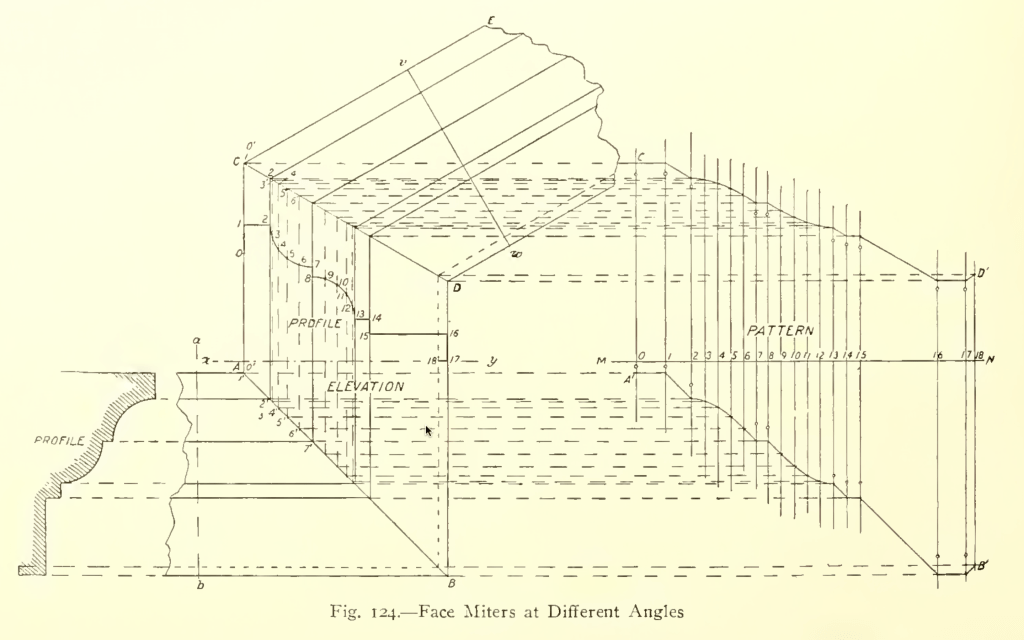
This is developed as is illustrated in Fig. 202, which shows the plan and elevation of an inclined mold mitering against the side of a column.

In the plan, A B represents the surface of a wall against which the back of a half round column X and also a mold Y are placed, the molding being inclined at the angle shown in the elevation, where the intersection of the two is shown at C D E. At Y of the plan is shown a profile or right section of the mold of which a b is the back or part in the plane of the wall surface, the plane of the section being revolved upon a horizontal line as a c until it is bought into the plane of the view, that is, the plan. In the elevation a’ b’ represents the line upon which the section is taken and upon which it is revolved to bring it into the plane of the elevation, as shown at Z.
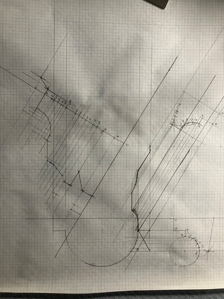
With these relations well understood, the method of deriving the pattern is as follows:
First divide the curved portions of profiles Z and Y into the same number of equal parts, numbering the points in each profile to correspond with the other, and from the points thus obtained upon profile Y carry lines parallel to the wall line to inter- sect the profile of the column, as shown from G to H.
From the points on profile Z carry lines from all points indefinitely, parallel to the lines of the mold, across the space above the plan of the miter.
Then erect lines from all of the points previously obtained in the plan to intersect corresponding lines brought from profile Z, as shown at C D E.
A line traced through these intersections will give the elevation of the miter. The pattern is obtained in the usual manner, by setting off a stretchout of the profile upon any straight line drawn at right angles to the mold in elevation, as M N, and projecting the points just obtained in the miter into measuring lines of corresponding number, as shown at C1 D1 E1
The intersection of the top part or roof of i b’ of the profile, with the side of the column, presents some peculiarities which it is well to consider, although that part is governed by exactly the same rules as are the other parts of the profile. This part of the profile, although straight, must be divided into spaces, not because of any curve in it, but because it is to be mitered against a profile which is curved in plan. It must therefore have upon it, first, points which correspond with the angles or members of the profile against is to miter, and, second, points in that part which abuts against the curve of the column, which are close enough to yield an accurate outline in the pattern It will be noticed that the fillet 7 8 of the profile is so designed as to be flush with a similar member in the plan of the column shown by c f.
That point in the profile of the roof 1 V, which will be cut by the surface e f of the column, can therefore be found by extending the line 7 8 of the profile up to intersect the roof line, as shown at point 7′. The remainder of the roof line, the part from point 7′ to I, can then be divided into spaces, according to convenience.
A simple way is, when extending the line 7 8, to also carry up lines from
the points 2 to 6 on the curve below, or as many of them as may be be deemed necessary, as shown, when the spaces from 1 to 9/ must then be set off on the stretchout line, as shown, being careful that the spaces as they occur are carefully measured, since they are likely by this method to be unequal in length.
The points on the roof can be numbered the same as those in the lower part of the profile from which they are obtained, adding primes (‘) to them, if deemed necessary, to avoid mistakes. The intersections between c’ and D of the miter will then follow the usual rule, by being made between lines of corresponding number.
The natural result of the development is to cut the fillet 7 8 from point Ja to E in the elevation of the miter, as shown by the dotted line between points of those numbers in the pattern. The extra thickness of metal caused thereby is the space ~a 7″ E of the elevation can be avoided by also projecting the point 7″ into the line 7 of the pattern and making the cut as there shown.
O D1 E1 K L will then be the pattern sought, to which the necessary edges or laps can be allowed.


You must be logged in to post a comment.